WikiDevi.Wi-Cat.RU:Network/Hardware modifications/Linksys WRT54G-TM/SD/MMC mod
Process developed by Doramius
Wiki created by Doramius
Copied from Linksys WRT54G-TM SD/MMC mod
NOTE: The SD card needs to be formatted ext2.
Parts
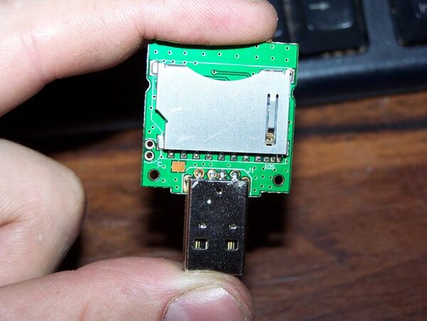
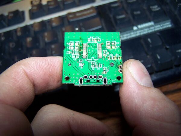
I'll mostly post pictures of the build I did. I had gone to Walmart and picked up a cheap Targus HighSpeed USB > SD/SDHC/MMC Card Reader/Writer. The case opened up really easy.
I went straight to work removing all components, except for the card slot, from the board. Solder braid works best, but even after I wicked off the leads to the chip, I still had to gently use a razor blade to slice under the leads to remove it. I also used a continuity tester to make sure there were no shorts from pin to pin. Pins 3 & 6 WILL short, but they are both Ground/Common. So no worries there.
GPIO Pinouts
Here's the pinout for the SD card and the GPIO points:
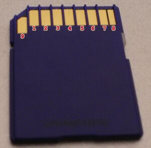
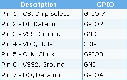
GPIO Solder Points
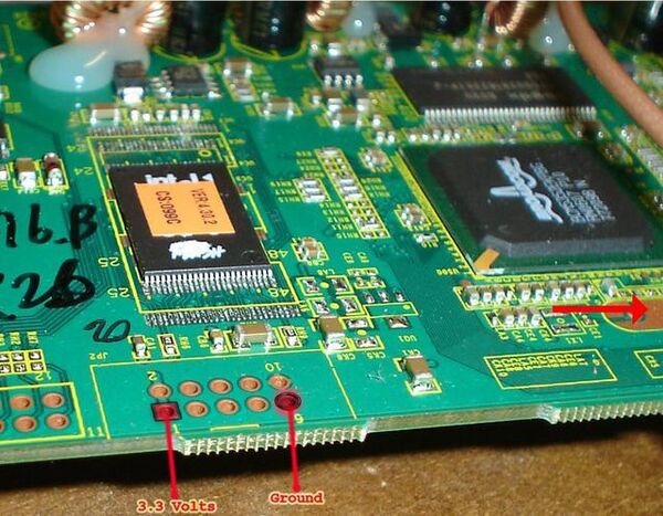
Now where the GPIO points are....? These little images made them quite easy to find. I still tested them to make sure they were correct. And they were.
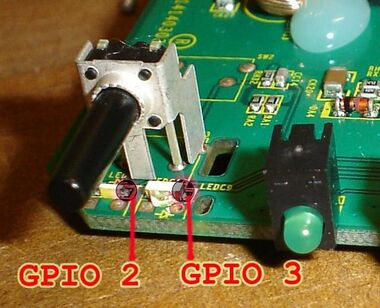
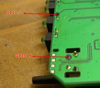
However, Instead of the ground at the JTAG headers, I found and tested this large, unused, copper pad for ground. It's the middle pad that comes out to a 'T'. (arrow off to the right) I didn't want to use the headers in the event I needed to install a connector.
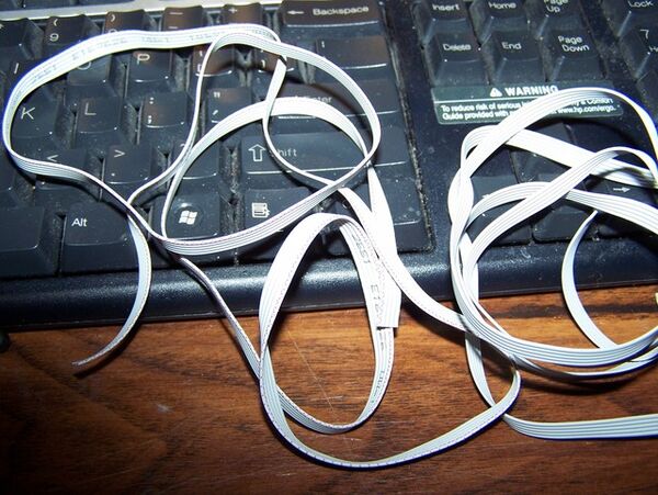
Now I had some ribbon cable left over from when I built my JTAG/TTL box.
Mounting the Card Slot
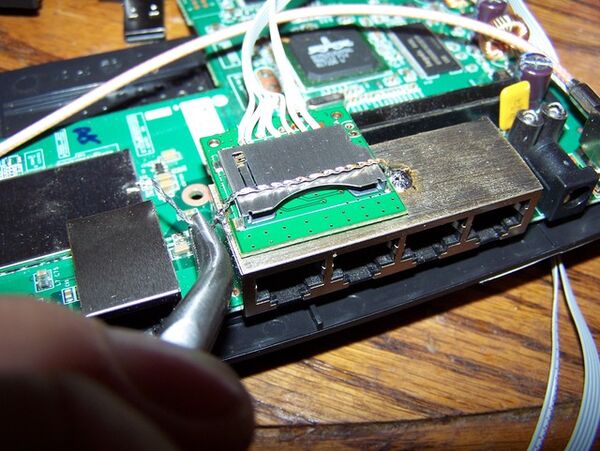
I needed to mount the SD slot somewhere and chose over ports 1&2, as the bracket served as a nice size mounting point. I lightly sanded the top, so it would take solder. And then placed the SD slot between to place solder at points for a hold-down.
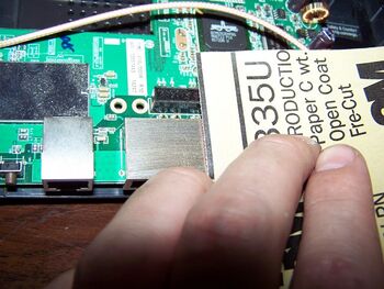
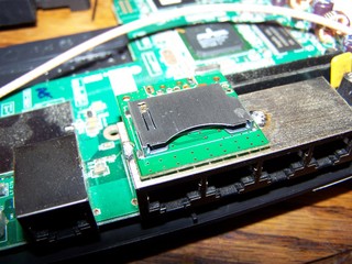
I then soldered the ribbon cables to the SD slot pins on the top of the mini-board. Not an easy job as they are pretty small. Next I took a piece of thin double sided tape and placed it on the bottom of the mini-board the SD slot was attached to. This did 2 things. Kept the port bracket from shorting the pads on the mini-board and stuck the board to the bracket. {Note} make sure your mini-board is not all the way to the other edge. You should be about 2mm from the edge as the case will slide about that distance over the edge of the bracket. I then took 2 solid strands from a twisted pair cable, stripped them, twisted them together, and soldered them together. This was my hold-down. I soldered the inside first, placed the mini-board on the bracket, and then soldered the other end at the edge of port one on the bracket. I left a bit of a tail so I could use pliers to pull the end firmly down to make sure it would solidly hold the slot in place. Sliding the cards in and out can cause quite a beating. The double sided tape and the hold-down will make sure the slot stays firmly affixed.
Putting it all Together
I then soldered the points as shown. Also note, that there are through-hole points near the LEDs. Use those as you don't want to remove an LED, or cause any damage to them. It also keeps the wire underside as some cases have plastic parts that mount right over the LEDs.
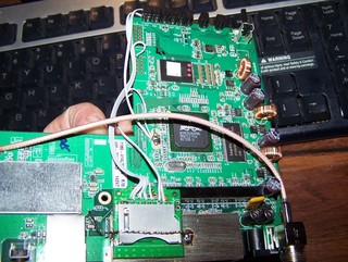
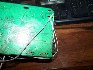
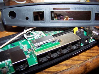
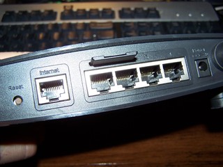
Next I brought out my trusty Dremmel and, after careful measurement, cut out the slot in the case where the card would go in. I made the slot about 2mm wider than the card on the sides. Giving a 1mm space on either side.
Time to put it all together.
Enabling the SD/MMC Card
Now that it's all done, physically, it's time to plug in an SD or MMC card and test it out with a PC.
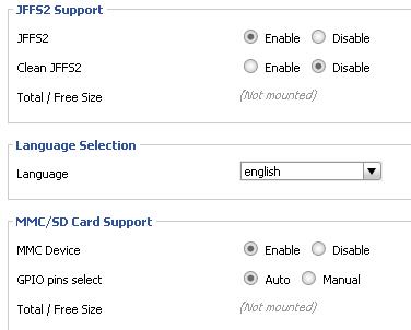
When I first plug it in, I notice it takes a little longer to load this first time. The SES light may or may not come on and flash a few times. This is normal. Just wait for the Power, Wireless, and the port light, corresponding to the port your PC is connected to, are all on and steady. If the SES light came on, with for it to steady. Log into the DD-WRT page. Go to the Administration tab and scroll down to MMC/SD Card Support areas. Enable it. I left the GPIO pins select at auto and it worked fine, but if you need to, the GPIO points are listed above. I also enabled the JFFS2, and you can also enable CIFS Automount, if desired.
Once you apply the settings, let it complete to reload the page. it may take a few minutes. The page may come back with data missing. Again, this is normal. Go to your router and press and hold the reset button for 30 seconds, while still holding the reset button, unplug the power and wait 5 more seconds before releasing the reset button. Now plug the power back in and let the unit load.
Again, this may take a few moments as it formats the card. The SES will probably come on, and rapidly flash for a bit, then turn solid. Wait for the Power, Wireless, and the PC connected port light to come on, steady. Now log back into DD-WRT and check the status. Any enabled items should show space usage listed.
Alternately, you can format the SD card yourself. The file system needs to be ext2.
The SD card is automatically mounted under /mmc at boot time.
Other Notes
Need to find and post working process to change the default available memory from 4608kb for larger SD/MMC cards.
Can anyone document the setup of an FTP server on the box with the Standard dd-wrt image.
Important Links
Forum Reference Link: http://dd-wrt.com/phpBB2/viewtopic.php?t=40464
LAST UPDATE: 11/7/08 9:40PM PST
