WikiDevi.Wi-Cat.RU:Network/Hardware modifications/Add 30 GPIO pins to a WRT54G
Source: Add 30 GPIO pins to a WRT54G
by SteveDiRaddo on Dec.03, 2008, under Hacks and Mods
If you are like me and can’t stop tinkering with your router, you’ll love this. Basically I took an old AVR (left over from the old nagra1 testing days), reprogrammed it, and attached it to my WRT54G. The result? 30 GPIO pins that are braindead-easy to control. The power of these little buggers is extreme. With a little extra programming these pins can control PS/2 keyboards, LCD modules, speakers, or even (with a little extra circuitry) small DC motors.
As it is now, however, I’m concentrating on LEDs and relays and such, just for now, to see how it goes. In this article is everything you need to attach one of these suckers to your serial-enabled router.
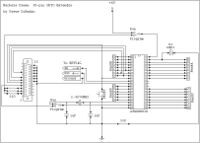
Correction: In the diagram Port D does not start at pin 1 (square block). It is pin 3. Pin 1 and 2 are the serial lines and are not available for GPIO. Correction: the picture has been updated to connect the AVR ground. Please ignore the previous diagram and use this one instead. Otherwise it will not work.
Introduction
As you can see in the diagram, this is everything you need to program and use your GPIO extender. The serial lines connect directly to the WRTs mainboard. Both the AVR and the router use TTL levels, so no converter chip is needed. There is a small problem though. Some AVRs (like the 8515-8PC) need at least 4 volts to operate, and the router only supplies 3.3 volts. The only way around this without using batteries is to install a 5 volt regulator in the router. I don’t have one, so I can’t show you exactly how. I opted for the battery method instead, my router being an already-battery-powered hybrid.
Programming
The circuit includes a FunCard-compatible basic LPT programmer. Programs like IcProg can be used to get the job done, no problem. Just be sure to set the switches to ‘Program’ to disable the high-power supply and external clocks. Failure to do this may result in damage to the parallel port, or a corrupted flash. Just set the switches to ‘Run’ and press the reset button to start the device. The source code (ASM only for now) is available for download at the end of the page. I used FastAVR to write the code, so if you don’t have it, get it. When I begin releasing the basic source, you will need it to compile.
Controlling the AVR
The AVR takes a single byte to control. It uses TTS1 at 9600,8,n,1 to communicate with the router. Each pin is mapped arbitrarily to an ASCII character. Uppercase letters set the appropriate pin high, while lowercase letters set the appropriate pin low. For example, ‘M’ will set Port B pin 5 high, while ‘m’ will set the same pin low. The full chart is at the end of this page.
If you are reading this you probably already have linux running on your router. Login through telnet and run the following command:
echo ^ /dev/tts/1
This will send the blink command to the AVR. If your wiring, programming, and power supply are good, the LED in the circuit should blink twice. Because I’m having a little trouble with the code, I had to leave Port A pin 8 and all of Port D disabled for now. You can also send strings of commands to do more than one pin at a time. For example, sending ‘TUmb’ will put C-3 and C-4 high and put B-4 and A-1 low. All you have to do is write a script for the router to do what you want it to.
Enjoy.
GPIOX build 120608 (.hex)
GPIOX control chart
atmel, gpio, wrt54g

