WikiDevi.Wi-Cat.RU:Network/Hardware modifications/Void Main's WRT54GSv3 USB Mod
Source: http://voidmain.is-a-geek.net/wrt/wrt_usb_mod.html
When might you use this tip?
- You need access to USB devices
Pros: Low cost and adds functionality
Cons: USB 1.1 only.
Tools/parts Required:
- WRT54GSv3 (although this can be done on other models but some can be much more difficult)
- soldering iron.
USB circuit:
1 - solder breadboard
4 - 15k ohm resistors
4 - 22 ohm resistors
2 - USB 4 pin motherboard headers
2 - USB-A female to motherboard 4-pin header connectors
5v supply circuit (you could run an external 5v power supply instead of this):
1 - 7805 regulator IC
1 - heat sink for 7805 regulator
1 - 100 uF electrolytic capacitor, at least 25V voltage rating
1 - 10 uF electrolytic capacitor, at least 6V voltage rating
1 - 100 nF ceramic or polyester capacitor
- 12V2A+ power supply to replace 1A (if you went with the above 5v circuit and significant USB PWR needed, I'm running stock power supply with no problem to power thumb drive, etc)
-- OR --
- 5V2A external power supply and female PCB pwr connector (if using separate exteranal 5v power supply)
Let us begin:
NOTE: Click on the thumbnail images in this tip to zoom in on the image.
This is a WRT54GSv3 running OpenWrt 8.09.2 with 2.4 kernel.
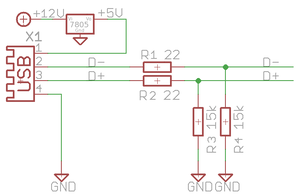
Basic circuit:
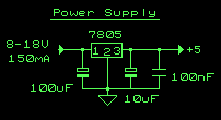
5v circuit information that should be incorporated into the above circuit diagram (Click image for web page with parts list and more info):
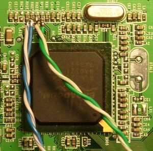
RH21 = USB1 D+ (green wire)
RH23 = USB1 D- (green/white wire)
RH25 = USB2 D+ (blue wire)
RH26 = USB2 D- (blue/white wire)
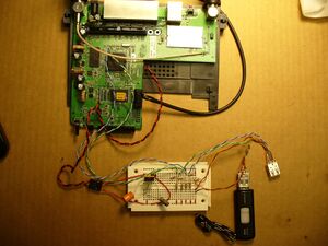
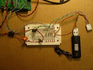
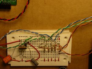
Mock-up on a breadboard. I went with color coded wires pulled from Cat5 cable to make it a little easier to document for this HOWTO. These wires are stiff and probably not the best choice for this project, especially to solder to the USB circuit on the WRT PCB.
Color Coding:
Red wire - 12v soldered to + terminal of 12v power connector on WRT
Black wire - Ground soldered to - terminal of 12v power connector on WRT
Green wire - USB 1 D+
Green/White wire - USB 1 D-
Blue wire - USB 2 D+
Blue/White wire - USB 2 D-
Orange wire - 5v
Brown wire - Ground
Red/Green/Yellow jumpers have mixed use
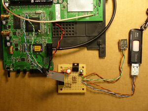
Soldered up on a circuit board. I used a 10 pin serial header to run all the wires from the WRT into so it can easily be disconnected. This was my first ever circuit build so there are probably man novice mistakes. Also might be a good idea to add a heatsink to the 7805:
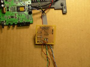
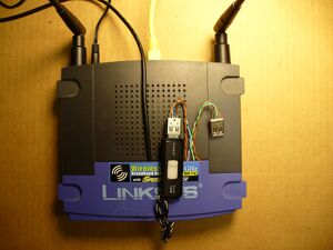
Not final mounting but usable:
When this mod is finished don't forget to install the extra USB packages:
opkg update
opkg install kmod-usb-ohci kmod-usb-storage kmod-usb-core
Many thanks to zerx for the help on this!!
zerx forum topic on OpenWRT forums
Further Reading:
Linksys GPL Firmware page (Thank you Linksys and thank you Richard Stallman (GPL)!!)
OpenWRT Web Site (my wireless web server runs it)
My revival thread (Thanks Jim!)
My wireless web server thread
Jim Buzbee's Linux on WRT54G page
Seattle Wireless WRT54G page
French Version of This (Thanks m.! Forum Topic)
P.S. SVEASOFT and Windows are not supported here.
Have fun!
