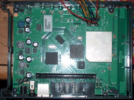
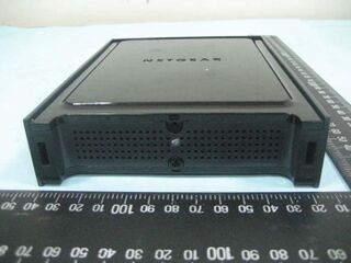
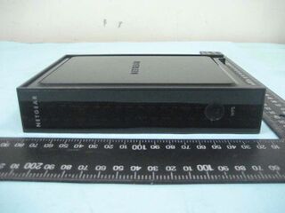
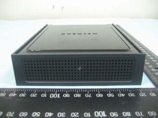
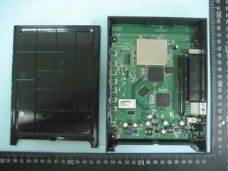
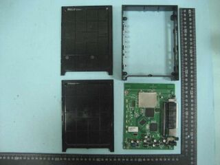
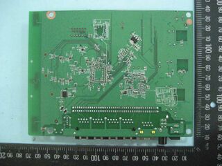
Netgear WNR3500v2
Netgear WNR3500 v2
Availability: Discontinued
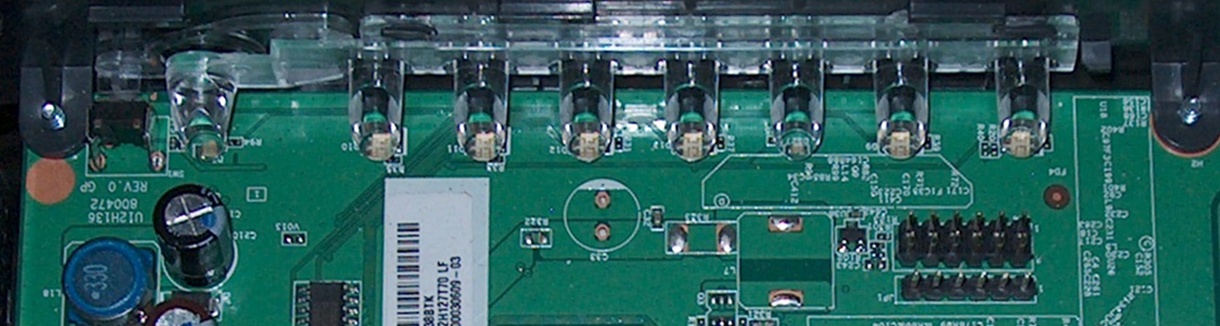
Manuf (OEM/ODM): Foxconn U12H127 T00
FCC approval date: 23 January 2009
(Est.) release date: 07 July 2009
Country of manuf.: China
S/N prefix: 25V20
Series: N300

Type: wireless router
FCC ID: PY308400093
IC ID: 4054A-08400093
PCB ID: U12H127T00
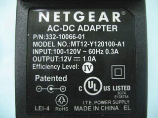
Power: 12 VAC ~ 60 Hz, 1.0 A
Connector type: barrel
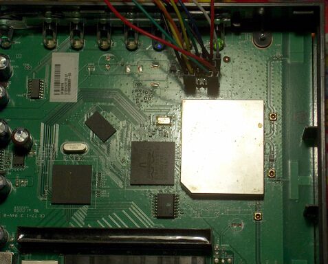
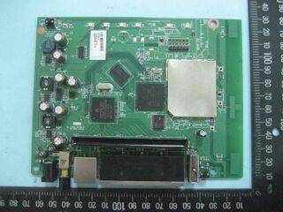
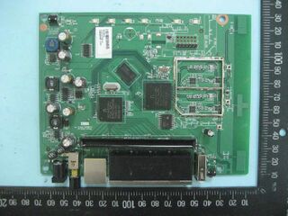
CPU1: Broadcom BCM4718A1 (453 MHz)
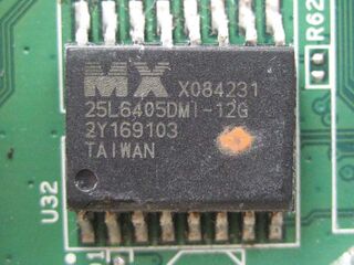
FLA1: 4 MiB4,194,304 B <br />32,768 Kib <br />4,096 KiB <br />32 Mib <br />0.00391 GiB <br /> (Macronix MX25L3205DMI-12G)
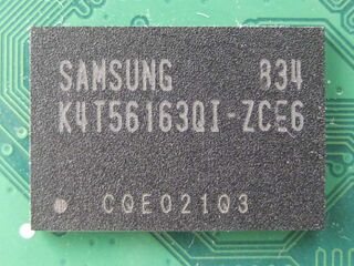
RAM1: 32 MiB33,554,432 B <br />262,144 Kib <br />32,768 KiB <br />256 Mib <br />0.0313 GiB <br /> (Samsung K4T51163QG-HCE6)
Expansion IFs: none specified
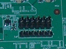
JTAG: yes, 12-pin header, unpopulated
Serial: yes, 6-pin header, unpopulated, (115200,8,N,1)
WI1 chip1: Broadcom BCM4718A1
WI1 802dot11 protocols: bgn
WI1 MIMO config: 2x2:2
WI1 antenna connector: none
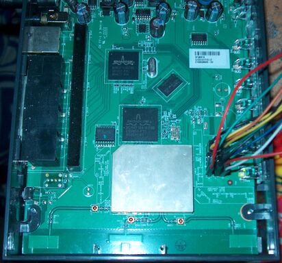
ETH chip1: Broadcom BCM4718A1
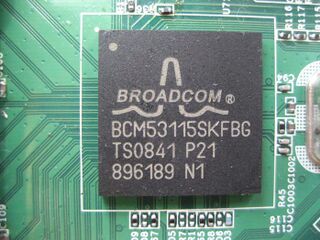
Switch: Broadcom BCM53115S
LAN speed: 1G
LAN ports: 4
WAN speed: 1G
WAN ports: 1
bgn
Stock bootloader: CFE (128k)
TPFirmware supported: FreshTomato • (List | DLs), DD-WRT • (List), Tomato (Shibby) • (List | DLs)
Flags: N300, WPS
Default SSID: NETGEAR (44 addl. devices)
Default IP address: 192.168.1.1
the IP 192.168.1.1 is used by 1304 additional devices
of which 106 are Netgear devices
Default login user: admin
Default login password: password
admin:password credentials used by 423 additional devices
of which 304 are Netgear devices
802dot11 OUI: C0:3F:0E (14 E, 12 W), 00:26:F2 (10 E, 10 W)
Ethernet OUI: C0:3F:0E (14 E, 12 W), 00:26:F2 (10 E, 10 W)
| FCC ID | |
|---|---|
| Netgear WNR3500Lv1 | PY308400093 |
| Netgear WNR3500U | PY308400093 |
| CPU1 brand | WI1 chip1 brand | WI1 chip2 brand | |
|---|---|---|---|
| Netgear WNR3500v1 | Marvell | Marvell | Marvell |
| Netgear WNR3500v2 | Broadcom | Broadcom |
For a list of all currently documented Broadcom chipsets with specifications, see Broadcom.
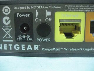
RangeMax Wireless-N Gigabit Router
Manuf. by Foxconn (Hon Hai) U12H127T00/U12H127T70
Models
| Netgear WNR3500v1 | WNR3500 | U12H092T00 (Marvell) |
|---|---|---|
| Netgear WNR3500v2 | WNR3500v2 | U12H127T00_NETGEAR |
| Netgear WNR3500v2VC (N.A.) | WNR3500v2VC | U12H127T70_NETGEAR |
| Netgear WNR3500U | WNR3500U | U12H136T00_NETGEAR |
| Netgear WNR3500L | WNR3500L | U12H136T99_NETGEAR |
| Netgear WNR3500Lv2 | WNR3500Lv2 | U12H172T00_NETGEAR U12H172T99_NETGEAR |
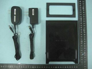
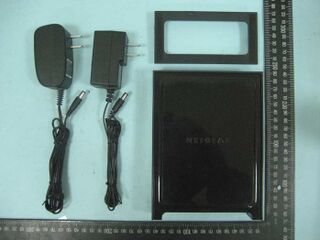
Power supply
- Input: 120VAC 1.5A @ 60Hz (N.A.) / 230VAC 1.5A @ 50Hz (Europe, U.K.) / 240VAC 1.5A @ 50Hz (Aus.)
- Output: 12VDC 1A
Flashing
| NOTE: During configuration or flashing a device, the only things that should be hooked to the device is the computer and power. |
Flashing DD-WRT
| WARNING: Requires K2.6 for DD-WRT, Do not flash anything else! |
- Perform a hard reset (30-30-30) on the device.
- Configure your PC for a static/manual IP address of
192.168.1.10. - Make sure nothing else but the power cord and your PC is connected to the router.
- Flash dd-wrt.v24-18946_NEWD-2_K2.6_mini-WNR3500v2.chk to the device.
- Wait five minutes.
- Browse to
http://192.168.1.1/and make sure you get the Change Password page. - Perform another hard reset (30-30-30).
- Browse to
http://192.168.1.1/, change the username and password, and re-configure the router.
Flashing FreshTomato
- FreshTomato hardware compatibility table note the following for this device:
- "Due to hard-coded jffs2 partition, flash size is reduced to only 3,473,408 bytes. As of v2022.5, FreshTomato MiniIPv6 builds (with the filename pattern
freshtomato-K26-NVRAM32K_RT-MIPSR2-<version>-MiniIPv6.zip) are 3,467,534 bytes and is the only image type that will fit. It will likely become necessary before long to look back to older releases in FreshTomato's download archive for images that are still small enough to fit it's available space."
Upgrading
Updating DD-WRT
If dd-wrt is already on the router follow these instructions. If stock firmware is on the router follow the flashing instructions.
- Check for recommended builds here first.
- Set your computer to a static IP of 192.168.1.7. (or to whatever subnet the router is on) Disable all firewalls and security. Disable wireless on your computer and only have the router connected to the flashing computer by the ethernet cable between the two.
- Hard reset or 30/30/30 (If the router supports it, if not, reset to defults in the GUI) prior to flashing. Wait. Check for password page on re-login and change password.
- Flash firmware. You can use the webgui except if you have a belkin router. (For belkin use tftp.exe to flash)
- Wait...at least three minutes. Lights should return to normal. See important2, below. Failing to wait is how most people brick their routers.
- Do a power cycle of the router. (Unplug the cord, count to 30 and plug it back in.)
- Wait for the lights to return to normal usually about 2 minutes.
- Hard reset or 30/30/30 again (If the router supports it, if not, reset to defults in the GUI). Wait. Check for the password page and re-login to change the password. Then you can reconfigure your settings manually.
- Once configured set your computer back to autoIP and autoDNS.
Important1: This Hard reset or 30/30/30 works fine for Asus router, but you do have to power cycle after the reset.
Important2: After you flash the firmware, and before you do the hard reset, the router will be building some nvram settings. YOU MUST WAIT FOR THIS TO FINISH PRIOR TO DOING ANYTHING WITH THE ROUTER INCLUDING A HARD RESET. Usually, you can tell when this process is completed by the WAN light coming on, but it does take several minutes. Go have a beer. There are starting to be more and more people who BRICK their routers by not waiting until the nvram is rebuilt, PRIOR to doing a hard reset. YOU NEED TO WAIT!}}
Reverting to stock firmware
- Adapted from NETGEAR's official documentation of the TFTP bootloader recovery process
The most robust method for replacing the stock firmware on this device in the event of a bad flash or a desire to stop using a third-party firmware is done using TFTP (Trivial File Transfer Protocol). Since most third-party firmwares do not alter the device's bootloader, this method can often recover devices that has ceased functioning correctly or even connecting to other devices. As a failsafe, the bootloader is designed to probe its LAN Ethernet ports moments into the start of every boot cycle for the presence of a TFTP server at the IP address 192.168.1.10, and if one is found, to request its file list and download the first file it encounters with either an .img or a .chk file extension and write its contents into flash memory. Assuming you're working from a modern Windows PC, the process tends to closely resemble this:
- Download TFTPD64 to your computer and make sure it executes successfully, then exit it for now.
- Downloads the OEM firmware from the Netgear web site and unzip the file (either with the Windows File Manager or a utility like 7-Zip) so that the
.chkfile in it is in a directory by itself. - Configure your computer's network adapter with a static/manual IP address of
192.168.1.10, subnet mask of255.255.255.0and a default gateway of192.168.1.1. Connect your network adapter to one of the router's LAN ports via Ethernet cable with the router powered off. - Launch TFTPD64 again and make sure the static IP address you just configured is selected in the drop-down menu labelled Server Interface. Configure the Base Directory for the server as the directory where you extracted the
.chkfile containing the OEM firmware to. - Power on the router. If the process begins successfully, within a minute of being turned on the power LED with turn orange and begin blinking, signalling that the bootloader found all the conditions needed to trigger the TFTP recovery mode and has begun the process of transferring the file and flashing itself with it. This will be briefly confirmed on the Server tab of TFTPD64 when the router appears in the connection list while it's retrieving the firmware file, and thereafter in the program's Log tab.
- Wait at least five minutes after the router closes the TFTP connection for the flashing process to complete and the router to reboot itself into the stock firmware; the process is complete when the Power LED has returned to steadily glowing white and the wireless network lights have turned on.
- Return to your network adapter settings and remove the static/manual IP address, subnet mask and default gateway entries, returning it to the "Automatic" or DHCP configuration mode.
- Open a web browser and go to the address
192.168.1.1to begin reconfiguring your router's new firmware.
From DD-WRT
No GUI reversion possible yet, see serial recovery for reversion.
Flash partitions
 dev:  size     erasesize name
 mtd0: 00040000 00010000 "pmon"
 mtd1: 00750000 00010000 "linux"
 mtd2: 005dc000 00010000 "rootfs"
 mtd3: 00080000 00010000 "jffs2"
 mtd4: 00010000 00010000 "nvram"
 mtd5: 00010000 00010000 "board_data"
Serial-JTAG Info
| NOTE: This section is assuming you know how to use the XVI32 Hex Editor, zJTAG and TFTPD64, as well as have a USB-/Serial-TTL adapter cable and/or a JTAG adapter. |
Serial pinouts
JP1
VCC 1 o RX 2 o N/C 3 o N/C 4 o TX 5 o GND 6 o |
J14
nTRST 1o o2 GND TDI 3o o4 GND TDO 5o o6 GND TMS 7o o8 GND TCK 9o o10 GND nSRST 11o o12 N/C |
Using a Universal JTAG Adapter
  white  1o o2	 black
    red  3o o4	 GND
   blue  5o o6	 GND
  green  7o o8	 GND
 yellow  9o o10  GND
 orange 11o o12  N/C
|
Using a TUMPA
TUMPA N/C 1o o2 N/C nTRST 3o o4 GND TDI 5o o6 GND TMS 7o o8 GND TCK 9o o10 GND N/C 11o o12 GND TDO 13o o14 GND nSRST 15o o16 GND N/C 17o o18 GND N/C 19o o20 GND |
Using the TUMPA's ribbon cable
- Black to your choice of pins 2,4,6,8,10 on the router and your choice of pins 4,6,8,10,12,14,16,18,20 on the TUMPA for GND (ground)
- White to pin 1 on the router and pin 3 on the TUMPA for the nTRST signal
- Grey to pin 3 on the router and pin 5 on the TUMPA for the TDI signal
- Purple to pin 7 on both devices for the TMS signal
- Blue to pin 9 on both devices for the TCK signal
- Green to pin 5 on the router and pin 13 on the TUMPA for the TDO signal
- Yellow to pin 11 on the router and pin 15 on the TUMPA for the nSRST signal
Hyper terminal Setup in Windows XP
In Windows XP, Click Start Button - All Programs - Accessories -
   Communication - HyperTerminal
Enter a name for the connection, Click ok
Choose com port you adapter is plugged into, Click ok
Set:
 Bits per second = 115200
 Data Bits = 8
 Parity = none
 Stop bits = 1
 Flow control = none
Click ok
Click File - Save As, and select a place to save it to so you
             don't have to enter the settings again.
Putty Setup in Windows XP
After installing putty, run it
 Serial line = The COM port your using for serial (ie. COM3)
 Speed = 115200
Click on Serial under Connection
 Serial line to connect to = same as above (Serial line)
 Speed (baud) = 115200
 Data bits = 8
 Stop bits = 1
 Parity = none
 Flow control = none
Click Session
 Enter a name for your connection under saved sessions
Click Save
Click Open
DD-WRT Serial Recovery
Once you're hooked up and seeing the data output into your terminal, power cycle the router and immediately start rapidly pressing Ctrl+C until it breaks the init process through to the CFE.
Using a Universal JTAG Adapter
Confirmed working with North American unit and firmware.
- Power Cycle,
tjtag3 -backup:cfe128 /silent /otheroptions - Power Cycle,
tjtag3 -backup:nvram /silent /otheroptions - Power Cycle,
tjtag3 -backup:wholeflash /silent /otheroptions - Power Cycle,
tjtag3 -backup:custom /window:0x1fc00000 /start:0x1c3e0000 /length:0x10000 /silent /otheroptions - The last step will backup the board data to "custom.bin, Using a Hex editer, check to make sure all the data looks similar to board_data.bin or post it to your thread in the dd-wrt forums and somebody can check it for you.
- If it is similar, change "U12H127T70_NETGEAR" to "U12H127T00_NETGEAR". The mac address starts at Hex address 40 in the middle pane, make sure it's correct. The Serial number starts at Dec address 76 in the right pane, make sure it's correct. The Security Pin starts at Dec address 108 in the right pane, make sure it's correct. The actual board data starts at Dec address 256 in the right pane, make sure it matches board_data.bin. If it looks all messed up then start fresh with board_data.bin and make all the changes to it. When done "save as" "custom.bin" without the quotes. Makes sure it's in the same folder as TJTAG.
- Now do the same with the cfe128, mac sure mac address match(although not as important with the cfe). Check to see if is similar to cfe128.bin. If not or it's just totally messed up use the reference cfe128.bin. Just edit it to match the information from your router.
- Power Cycle,
tjtag3 -flash:custom /window:0x1fc00000 /start:0x1ffe0000 /length:0x10000 /swap_endian /byte_mode /silent /otheroptions - Power Cycle,
tjtag3 -flash:cfe128 /swap_endian /byte_mode /silent /otheroptions - Have TFTP.exe ready in WindowsXP, with WNR3500v2-V1.2.2.28_25.0.85NA.chk from that zip file. Configure your computer with a static IP address of 192.168.1.10. Connect the router to the PC via network cable. Power on the router and when it signals a connection, click Upgrade.
USB
This device has no USB ports.
VLANs
DD-WRT VLAN Configuration
- WikiDevi:DD-WRT/VLAN Support Testing Needed
Notes
Identifying your router's model number
After spending an hour researching the variants of the Netgear WNR3500 family and their
- specs prior to a purchase, I realized this would he handy to post up somewhere.
So, I thought I'd table it up and share it, since there wasn't a concise guide anywhere
- on the web already. Hopefully this will help some people out!
| Model | Flash /RAM |
CPU | USB | Ant | WLAN | Eth | WAN | Notes | FCC ID |
|---|---|---|---|---|---|---|---|---|---|
| WNR3500 v1 | 8/32 | Marvell 88F5180NB1 @500 TopDog |
No | 2 int. | N300 | 4x GbE | GigE | Blue Antenna LEDs on top | PY307300074 |
| WNR3500 v2 | 4/32 | Broadcom BCM4718A @480 MIPS74k |
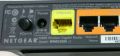
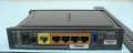
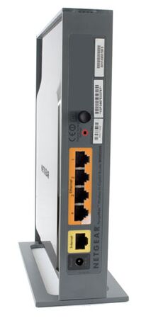
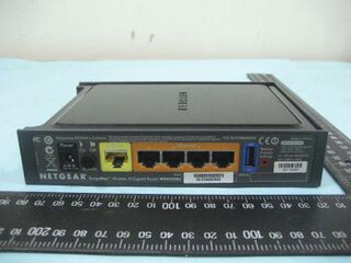
No | 4 int. | N300 | 4x GbE | GbE | "V2" marked under orange LAN ports, smaller housing, no antenna LEDs |
PY308400093 |
| WNR3500L V1 | 8/64 | Broadcom BCM4718A @480 MIPS74k |
1x USB 2.0 |
4 int. | N300 | 4x GbE | GbE | WNR3500U/WNR3500L Marked below yellow WAN port |
PY308400093 |
| WNR3500L V2 | 128/128 | Broadcom BCM47186B0 @480 MIPS74k |
1x USB 2.0 |
2 int. | N300 | 4x GbE | GbE | Below yellow WAN port WNR3500L v2 | PY310400153 |

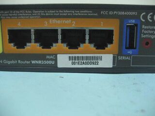
Picture of the back of WNR3500U/3500L v1
Picture of the back of WNR3500L v2
Picture of the back of WNR3500U

Closeup of label WNR3500U


Images
- Netgear Images


- DarkShadow's Unit


- FCCID PY308400093


See also
External links
DD-WRT Forum
- Netgear WNR3500 v2.0 Brick (solved)
- Netgear WNR3500 v2.0
- DD-WRT for Netgear WNR3500v2?
- Netgear WNR3500V2 - rollback to original FW
- Netgear 3500 v2 died after firmware upgrade
- WNR3500v2 stuck in waiting for tftp mode [Solved]
